
219mm Configuration
The inlet flange reference increases to A 300, B 350 and C 380 mm compared with the smaller pipe sizes.
The Φ219 mm screw conveyor is listed at a 40 t/h reference capacity. It appears among the powder-handling options for multiple mobile plant configurations.
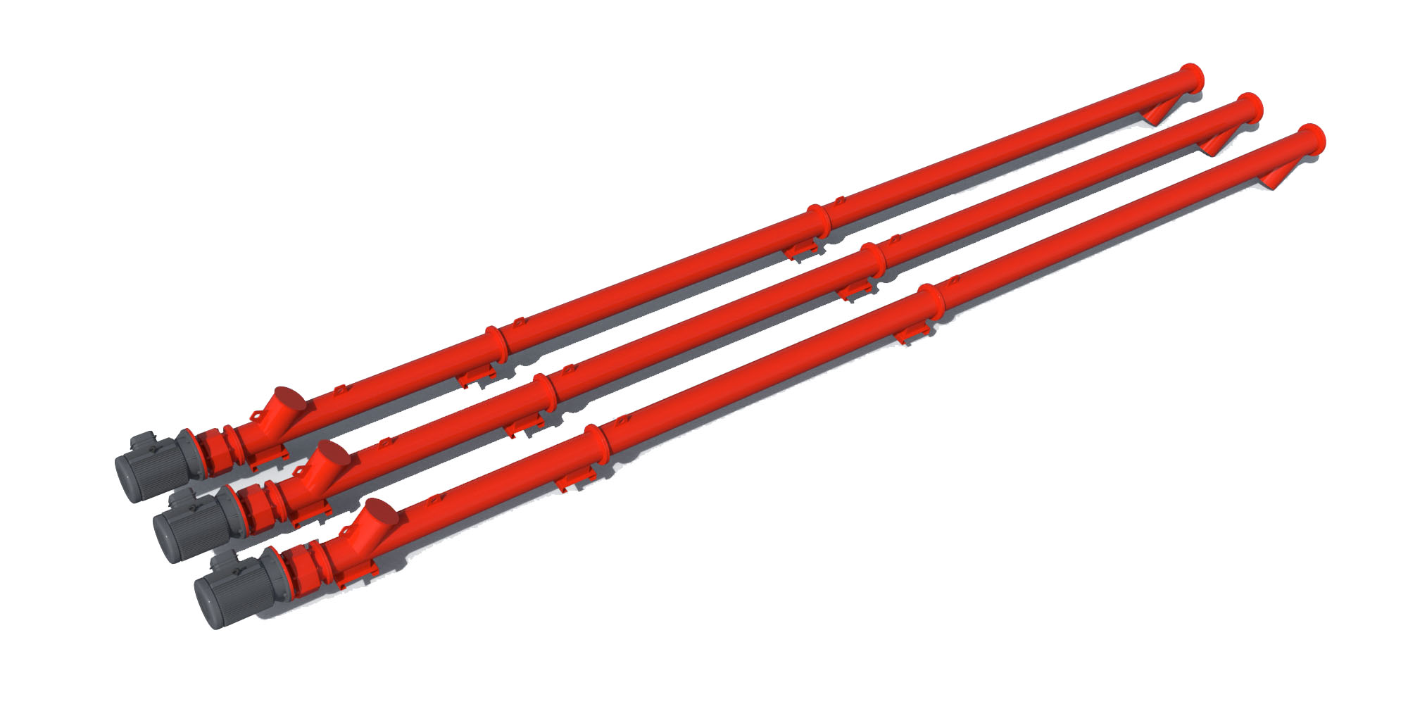
Series rendering. Confirm 219mm's appearance and included equipment in its proposal.
The Φ219 screw connects compatible storage and weighing equipment through an enclosed mechanical transfer route.
Review the 40 t/h reference with actual centre distance, powder density and inclination, including the published mobile-plant associations.
The inlet flange reference increases to A 300, B 350 and C 380 mm compared with the smaller pipe sizes.
Its published installation dimensions distinguish outlet heights across three inclination bands.
Understand the role of each connection before building the equipment package.
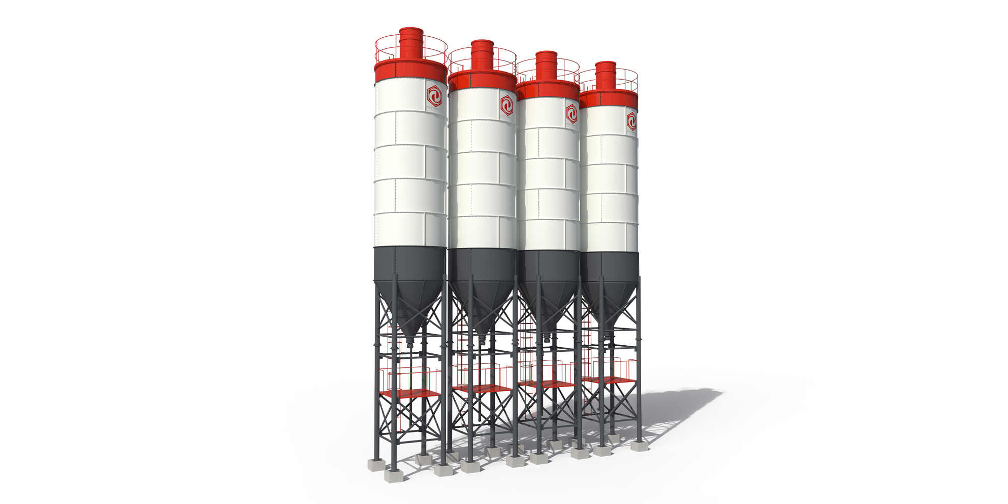 INTERFACE 01 / Cement Silo
The 50T, 80T and 100T references use this diameter in different combinations.
Storage tonnage alone does not fix the final drive.
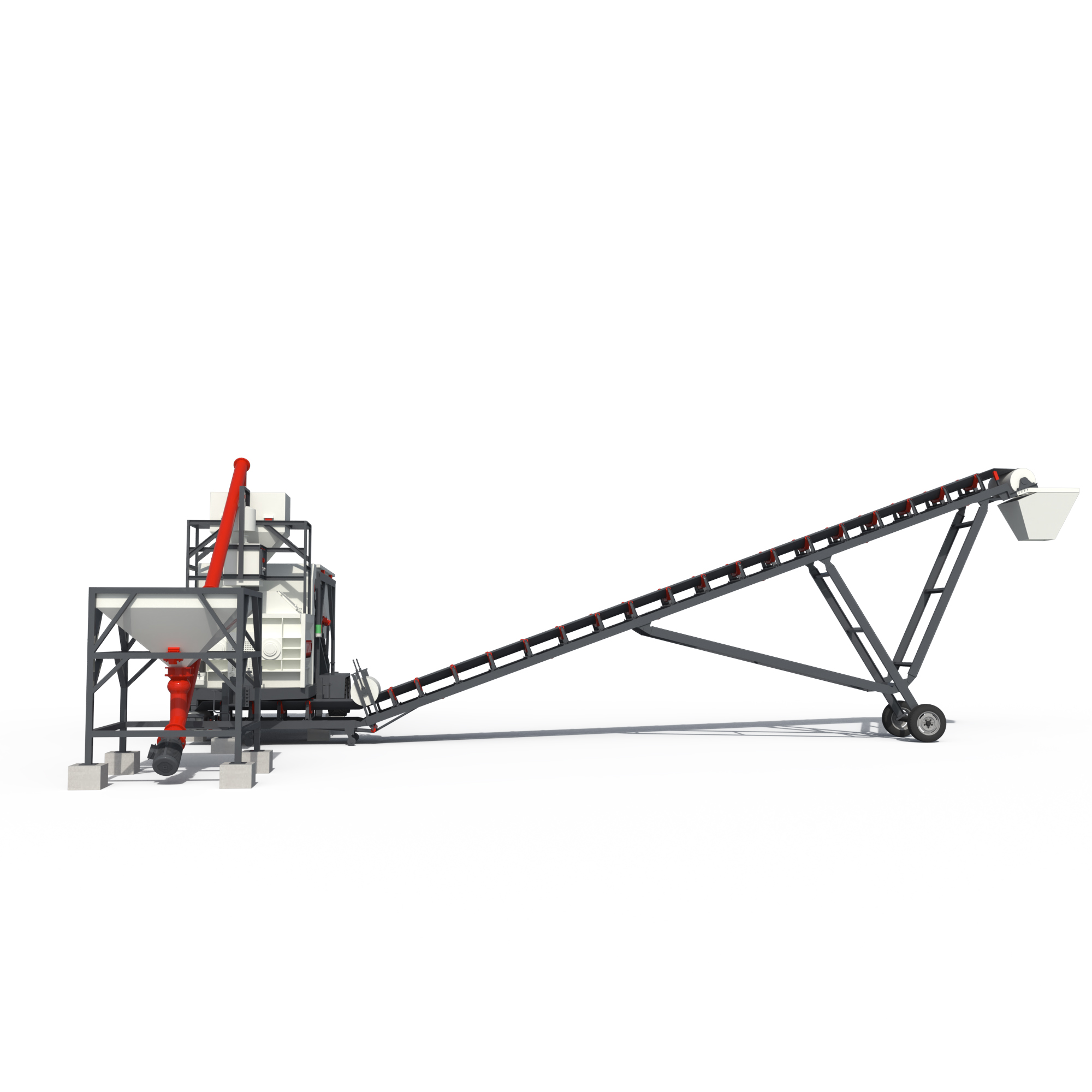 INTERFACE 02 / Mobile Concrete Batching Plant
Several YHZS tables identify a Φ219 × 12000 mm conveyor.
Confirm the current model layout and exact receiving interface.
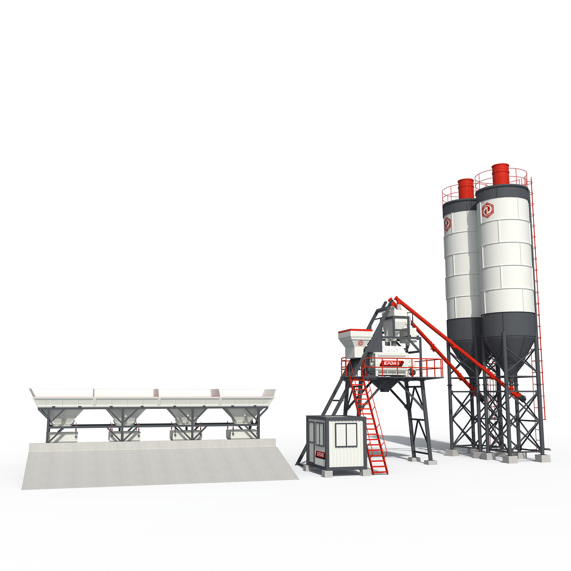 INTERFACE 03 / Stationary Concrete Batching Plant
Central batching requires controlled powder delivery to its scales.
Check whether the proposed cycle can be supported at the selected angle.
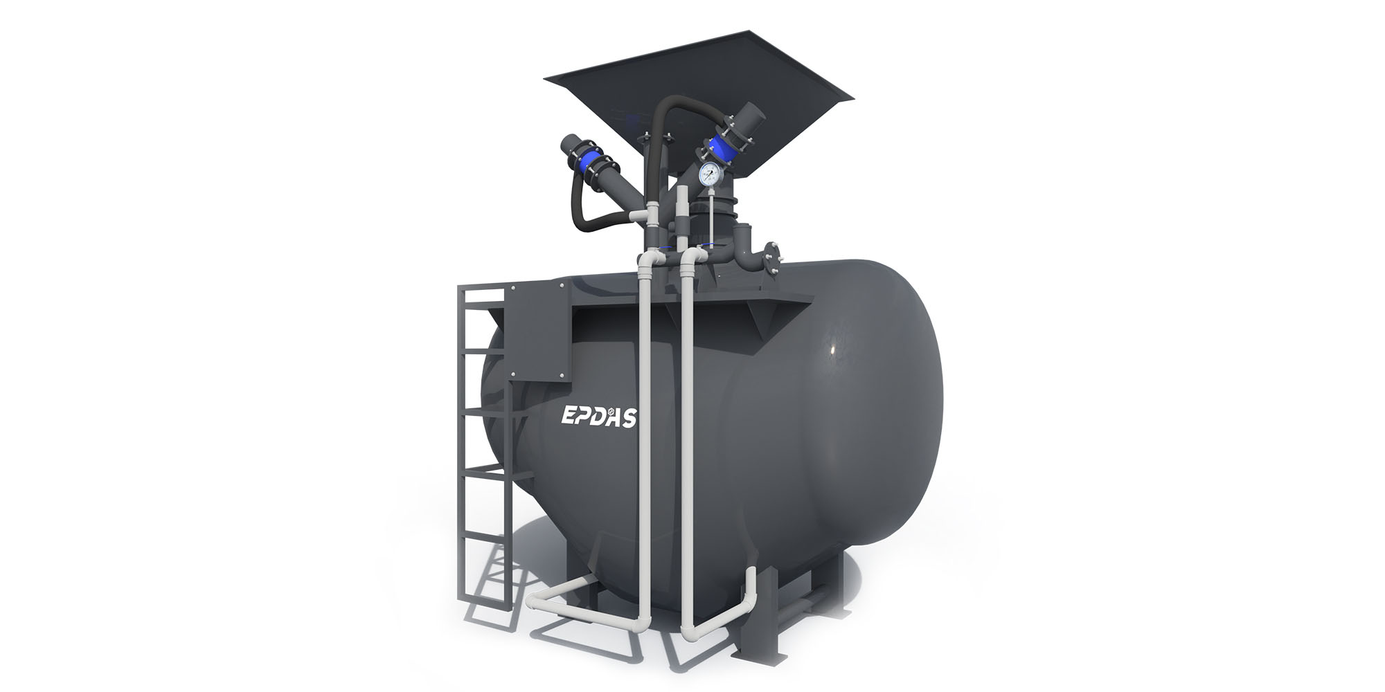 INTERFACE 04 / Cement Feeder
The conveyor is not a complete cement unloading system.
Document how cement reaches storage before sizing its discharge route.
Options and alternative architectures are identified in each explanation. This is not a pre-approved matched package. Final connections, duty and supplied components require a model-specific technical review.
Review My Equipment CombinationSeparate the key systems to see what each contributes to the operation.
219mm functional separation illustration. Blocks identify subsystem roles; they do not reproduce the machine geometry, assembly sequence or fastening details. Request the approved model drawing for engineering use.
| Parameter | 219mm |
|---|---|
| Inlet flange A (mm) | 300 |
| Inlet flange B (mm) | 350 |
| Inlet flange C (mm) | 380 |
| Inlet H1, 0–20° (mm) | 500 |
| Inlet H1, >20–40° (mm) | 550 |
| Inlet H1, >40–50° (mm) | 600 |
| Outlet H2, 0–20° (mm) | 300 |
| Outlet H2, >20–40° (mm) | 400 |
| Outlet H2, >40–50° (mm) | 450 |
| Reference capacity | 40t/h |
Published EPDAS specifications are a reference for equipment selection. Final specifications and included equipment are confirmed in the quotation. Conveying capacity depends on material, inclination, length and feed conditions. Installation flange dimensions must be checked against the final drawing.
Original EPDAS Technical Reference ↗| Selection reference | 219mm · This model | 168mm | 273mm |
|---|---|---|---|
| Reference capacity | 40t/h | 24t/h | 80t/h |
| Inlet flange A (mm) | 300 | 200 | 300 |
| Inlet flange C (mm) | 380 | 280 | 380 |
| Inlet H1, 0–20° (mm) | 500 | 400 | 500 |
| Outlet H2, 0–20° (mm) | 300 | 250 | 350 |
Compare Φ219 when connecting cement storage to a plant weighing system with a defined throughput and centre-to-centre distance.
Reference capacity: 40t/h
Confirm core equipment, options, buyer-provided systems, transport modules, inspection documents and support responsibilities in the quotation.