
HGY17 Configuration
The published 3.51 m tail rotary radius is useful for checking rear clearance around the boom.
HGY17 increases maximum radius to 17 m and lists a 4.6 × 4.6 m support-leg span. Its longer arm sections create a different working envelope from HGY15.
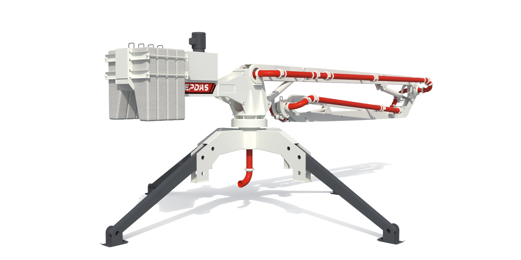
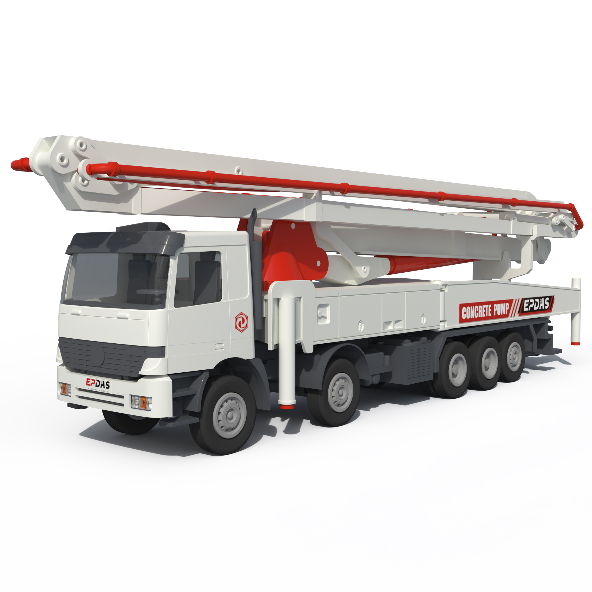
Series rendering. Confirm HGY17's appearance and included equipment in its proposal.
The listed 4.6 × 4.6 m support-leg span and 3.51 m tail rotary radius make HGY17 a distinct positioning study.
Assess its expanded working area together with rear clearance, lifting provisions and the proposed supply-pump duty.
The published 3.51 m tail rotary radius is useful for checking rear clearance around the boom.
The 5,000 kg bare-machine reference makes the lifting plan specific to this configuration.
Understand the role of each connection before building the equipment package.
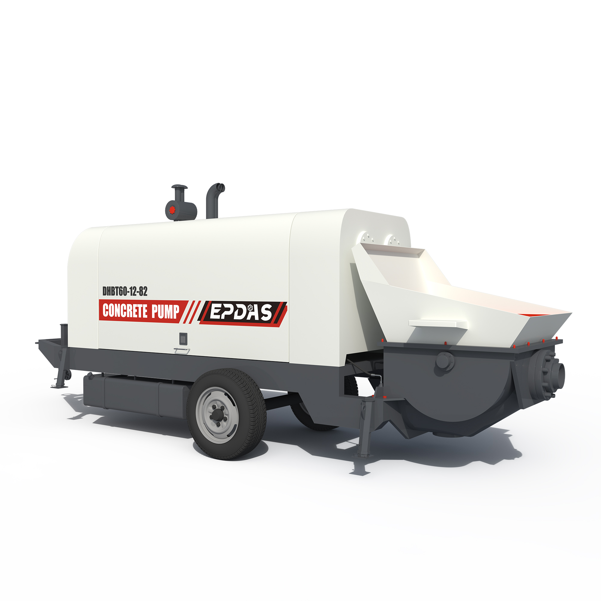 INTERFACE 01 / Trailer Concrete Pump
A supply pump and HGY17 form different parts of one delivery system.
Account for elevation and all distribution pipe sections when choosing the pump.
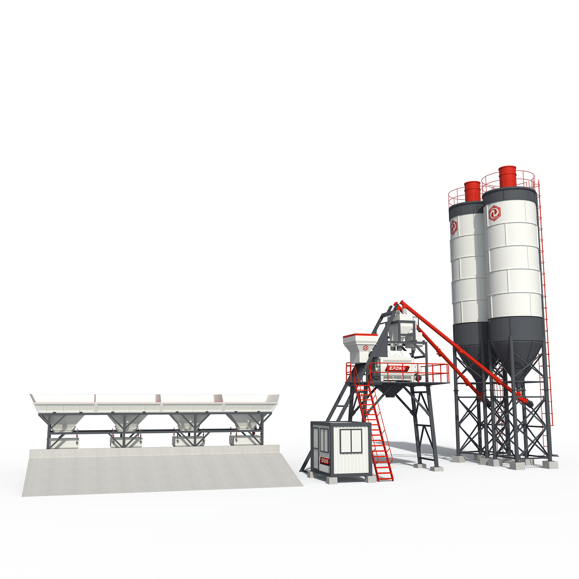 INTERFACE 02 / Stationary Concrete Batching Plant
Concrete production and fleet dispatch determine upstream availability.
Coordinate deliveries with the independent pumping stage serving the boom.
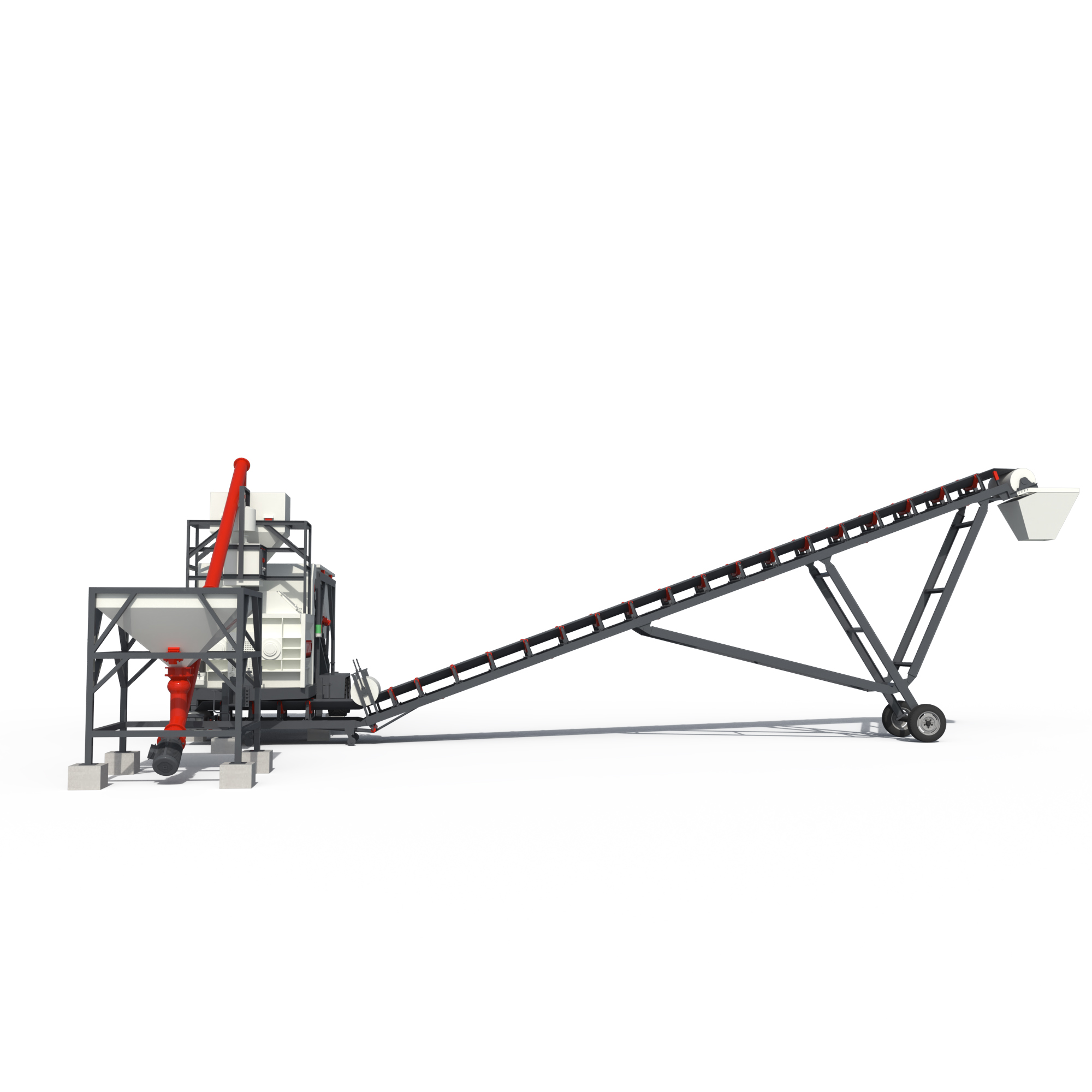 INTERFACE 03 / Mobile Concrete Batching Plant
A site plant may reduce the distance to the pump.
Verify the concrete transfer stage before fixing boom operating schedules.
 INTERFACE 04 / Concrete Boom Pump
Vehicle-mounted distribution has a different reach and support envelope.
Compare actual obstacles with the separate boom's tail clearance.
Options and alternative architectures are identified in each explanation. This is not a pre-approved matched package. Final connections, duty and supplied components require a model-specific technical review.
Review My Equipment CombinationSeparate the key systems to see what each contributes to the operation.
HGY17 functional separation illustration. Blocks identify subsystem roles; they do not reproduce the machine geometry, assembly sequence or fastening details. Request the approved model drawing for engineering use.
| Parameter | HGY17 |
|---|---|
| Max. placing radius (m) | 17 |
| Big arm length (m) | 6.66 |
| Big arm elevation (°) | 0~65 |
| Medium arm length (m) | 5.73 |
| Medium arm elevation (°) | 0~180 |
| Small arm length (m) | 4.61 |
| Small arm elevation (°) | 0~180 |
| Hose length (m) | 3 |
| Concrete delivery pipe (mm) | ø 125×6 |
| Tail rotary radius (m) | 3.51 |
| Total power (Kw) | 5.5/7.5 |
| System pressure (Mpa) | 24 |
| Rotary speed (r/min) | 0.3—0.8 |
| Rotary range (°) | 0~360 |
| Supporting legs span (m) | 4.6×4.6 |
| Overall height (m) | 3.2 |
| Bare machine weight (kg) | 5000 |
| Balance weight (kg) | 2200 |
| Control mode | Panel/ Wireless remote control |
Published EPDAS specifications are a reference for equipment selection. Final specifications and included equipment are confirmed in the quotation.
Original EPDAS Technical Reference ↗| Selection reference | HGY17 · This model | HGY15 | HGY21 |
|---|---|---|---|
| Max. placing radius (m) | 17 | 15 | 21 |
| Supporting legs span (m) | 4.6×4.6 | 4×4 | 5×5 |
| Tail rotary radius (m) | 3.51 | 2.81 | 3.93 |
| Bare machine weight (kg) | 5000 | 3230 | 6700 |
| Total power (Kw) | 5.5/7.5 | 4 | 5.5/7.5 |
Assess HGY17 when a wider concrete placement area justifies a larger support and handling arrangement.
Total power (Kw): 5.5/7.5
System pressure (Mpa): 24
Supporting legs span (m): 4.6×4.6
Confirm core equipment, options, buyer-provided systems, transport modules, inspection documents and support responsibilities in the quotation.