
HGY21 Configuration
A 5 × 5 m support-leg span sets the reference footprint for the engineering assessment.
HGY21 reaches a 21 m maximum placing radius through 8.66 m, 6.73 m and 5.61 m arm sections. It is the largest boom in the current HGY comparison.
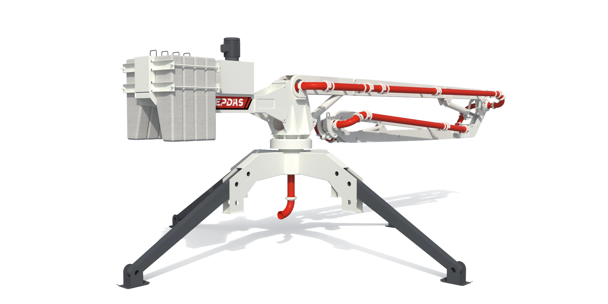
Series rendering. Confirm HGY21's appearance and included equipment in its proposal.
HGY21 combines 8.66 m, 6.73 m and 5.61 m arms for a 21 m maximum radius and a 5 × 5 m support-span reference.
Review wider distribution only after the position, lifting route and support design can accommodate this larger placing assembly.
A 5 × 5 m support-leg span sets the reference footprint for the engineering assessment.
The 3.93 m tail rotary radius and 6,700 kg bare-machine weight define additional clearance and lifting considerations.
Understand the role of each connection before building the equipment package.
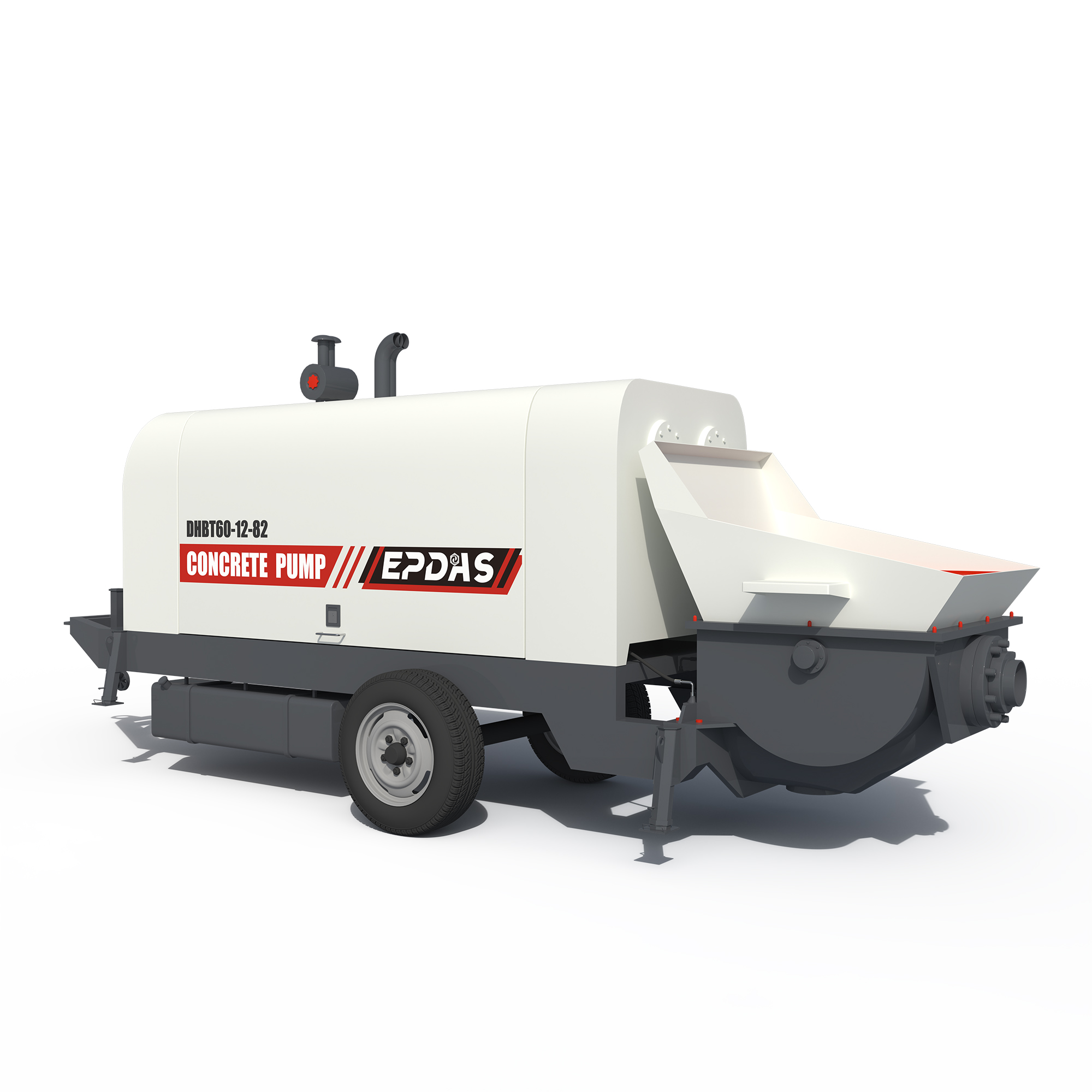 INTERFACE 01 / Trailer Concrete Pump
The receiving pump must serve the full route to and through HGY21.
Assess flow, line pressure and all connected pipe ratings together.
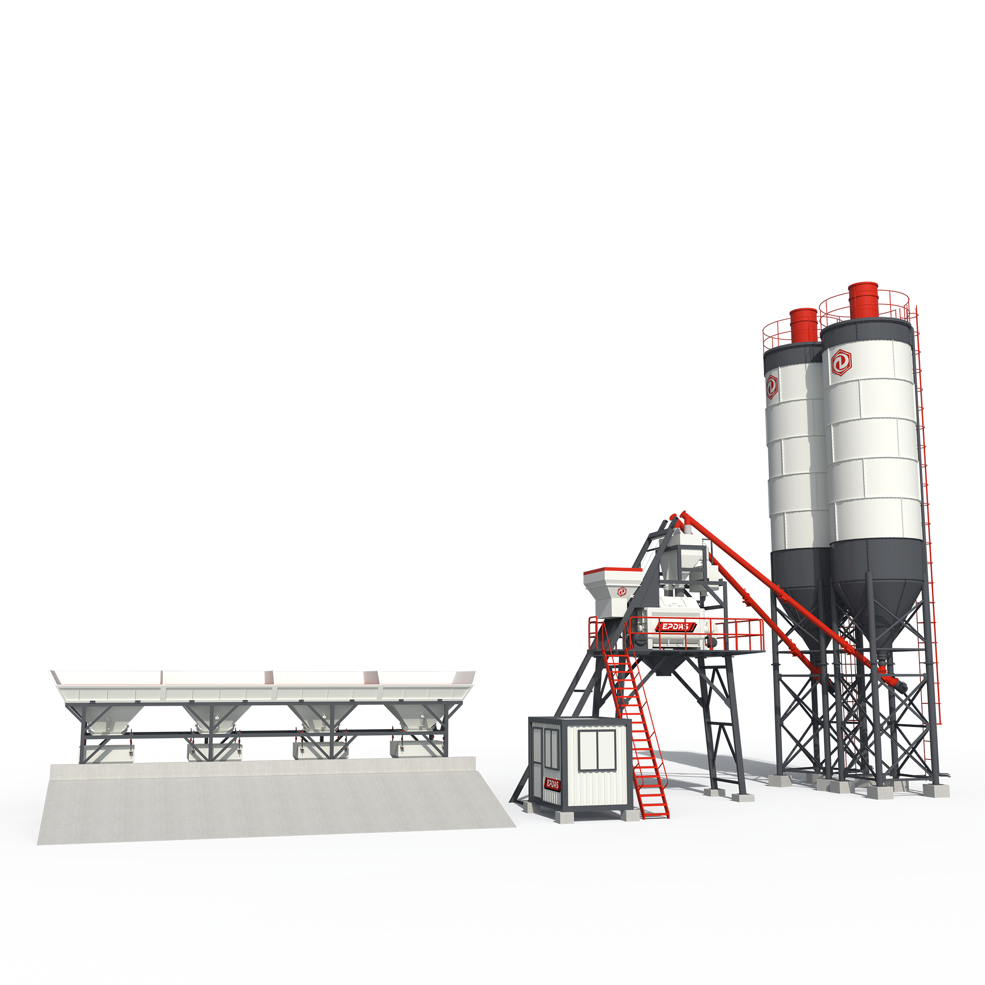 INTERFACE 02 / Stationary Concrete Batching Plant
A high-demand production base can supply the operation through trucks and a separate pump.
Plan that chain around the pour rather than radius alone.
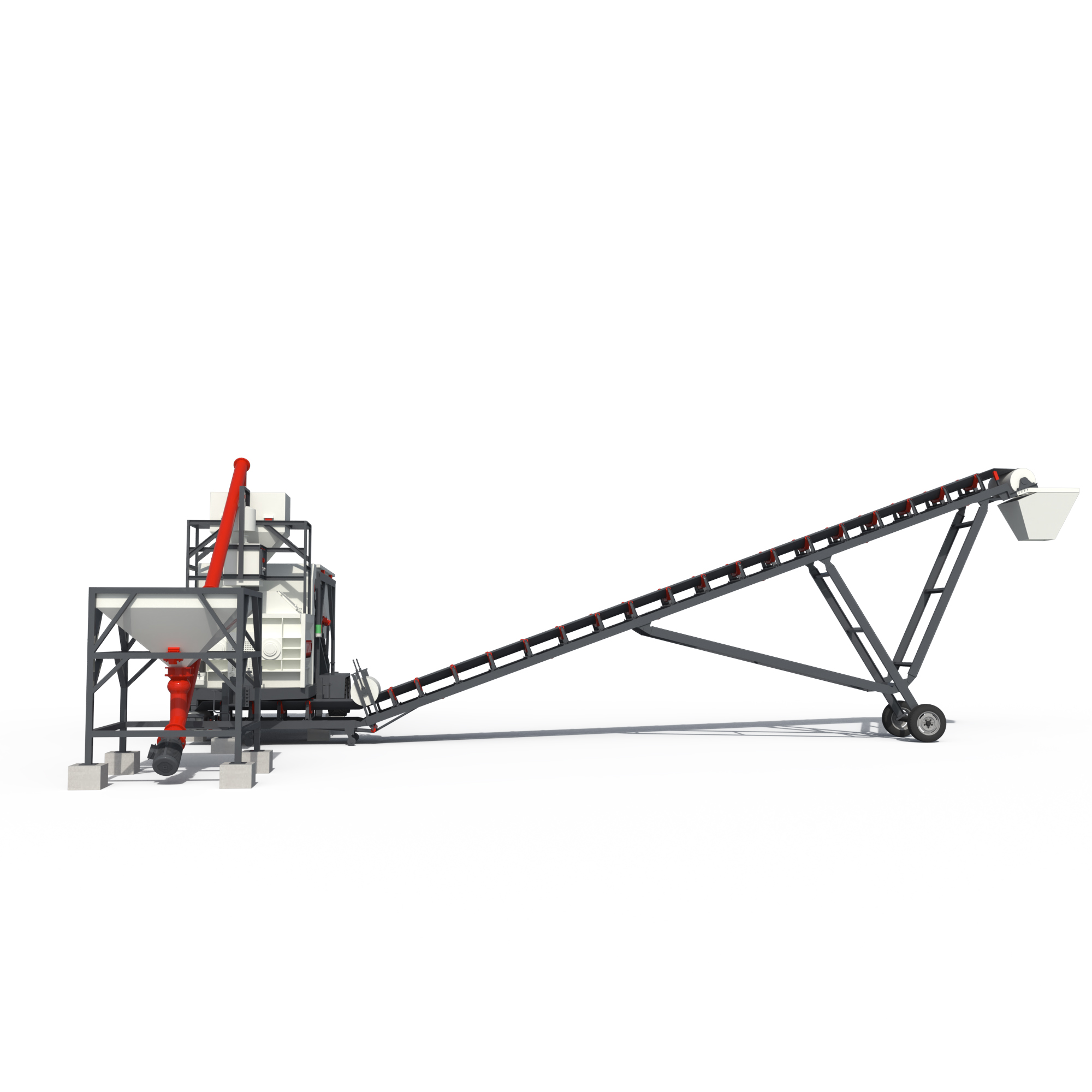 INTERFACE 03 / Mobile Concrete Batching Plant
Temporary local batching may feed the pumping station.
Define the receiving point and material continuity across each work stage.
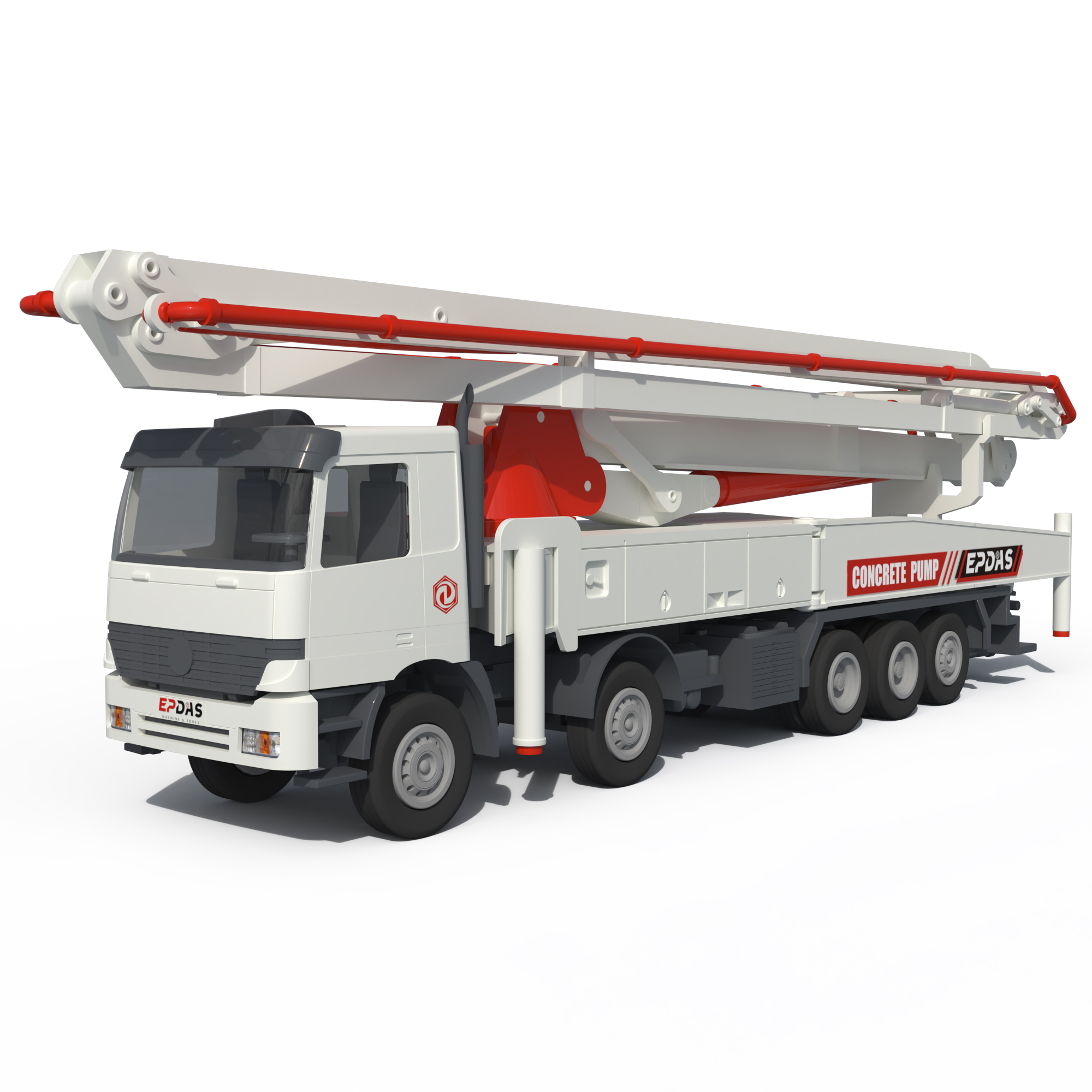 INTERFACE 04 / Concrete Boom Pump
A longer truck-mounted boom is another placing approach.
Compare truck access against the structural and lifting needs of the HGY21 installation.
Options and alternative architectures are identified in each explanation. This is not a pre-approved matched package. Final connections, duty and supplied components require a model-specific technical review.
Review My Equipment CombinationSeparate the key systems to see what each contributes to the operation.
HGY21 functional separation illustration. Blocks identify subsystem roles; they do not reproduce the machine geometry, assembly sequence or fastening details. Request the approved model drawing for engineering use.
| Parameter | HGY21 |
|---|---|
| Max. placing radius (m) | 21 |
| Big arm length (m) | 8.66 |
| Big arm elevation (°) | 0~65 |
| Medium arm length (m) | 6.73 |
| Medium arm elevation (°) | 0~180 |
| Small arm length (m) | 5.61 |
| Small arm elevation (°) | 0~180 |
| Hose length (m) | 3 |
| Concrete delivery pipe (mm) | ø 125×6 |
| Tail rotary radius (m) | 3.93 |
| Total power (Kw) | 5.5/7.5 |
| System pressure (Mpa) | 24 |
| Rotary speed (r/min) | 0.3—0.8 |
| Rotary range (°) | 0~360 |
| Supporting legs span (m) | 5×5 |
| Overall height (m) | 3.75 |
| Bare machine weight (kg) | 6700 |
| Balance weight (kg) | 2×1100 |
| Control mode | Panel/ Wireless remote control |
Published EPDAS specifications are a reference for equipment selection. Final specifications and included equipment are confirmed in the quotation.
Original EPDAS Technical Reference ↗| Selection reference | HGY21 · This model | HGY17 | HGY15 |
|---|---|---|---|
| Max. placing radius (m) | 21 | 17 | 15 |
| Supporting legs span (m) | 5×5 | 4.6×4.6 | 4×4 |
| Tail rotary radius (m) | 3.93 | 3.51 | 2.81 |
| Bare machine weight (kg) | 6700 | 5000 | 3230 |
| Total power (Kw) | 5.5/7.5 | 5.5/7.5 | 4 |
Evaluate HGY21 for an extended placing area supplied by a compatible separate concrete pump.
Total power (Kw): 5.5/7.5
System pressure (Mpa): 24
Supporting legs span (m): 5×5
Confirm core equipment, options, buyer-provided systems, transport modules, inspection documents and support responsibilities in the quotation.