
HBT60S-13-90 Configuration
Separate 180 m vertical and 700 m horizontal references support a detailed route discussion.
HBT60S-13-90 combines a 90 kW motor with 60 m³/h theoretical delivery. The source gives a 12.5 MPa maximum pressure despite the rounded pressure figure in the model name.
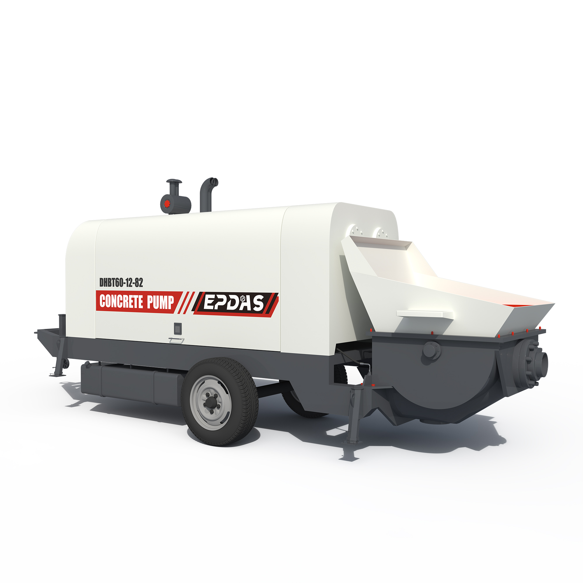
Series rendering. Confirm HBT60S-13-90's appearance and included equipment in its proposal.
This HBT60S configuration combines 60 m³/h theoretical delivery with a listed 12.5 MPa maximum pressure.
Review steady external supply and a site electrical design suitable for the larger motor, without interpreting the rounded model number as exact pressure.
Separate 180 m vertical and 700 m horizontal references support a detailed route discussion.
Its 600 L hopper and Φ125 delivery-pipe reference align with the larger electric HBT configuration.
Understand the role of each connection before building the equipment package.
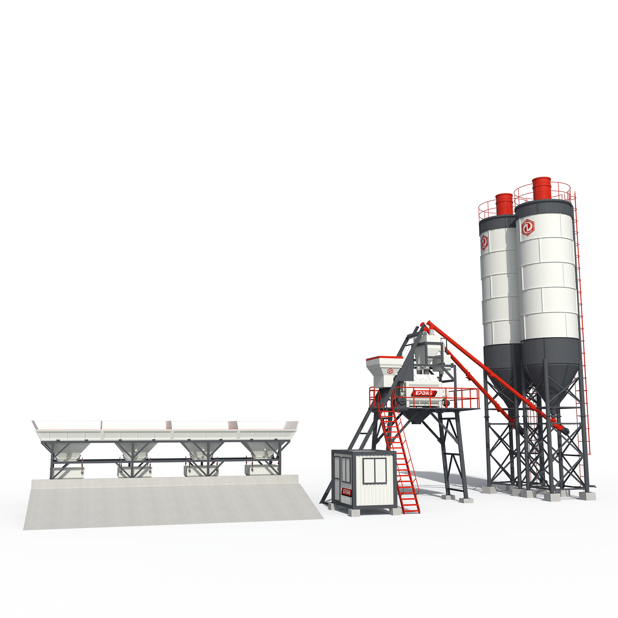 INTERFACE 01 / Stationary Concrete Batching Plant
Central production can supply the receiving fleet.
Compare actual concrete arrivals with the planned 60 m³/h delivery class.
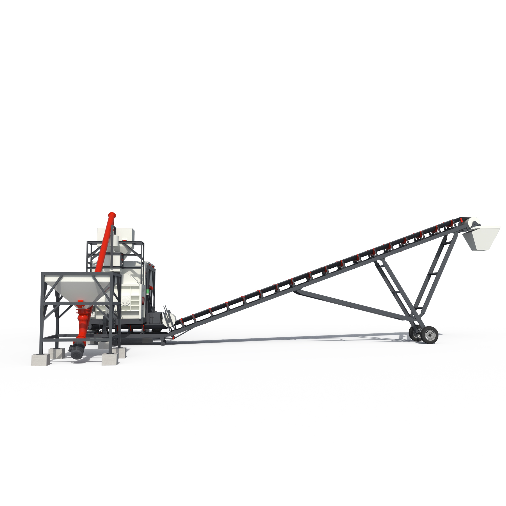 INTERFACE 02 / Mobile Concrete Batching Plant
Mobile production provides an alternative site source.
Verify concrete receiving elevation and supply continuity before selecting the package.
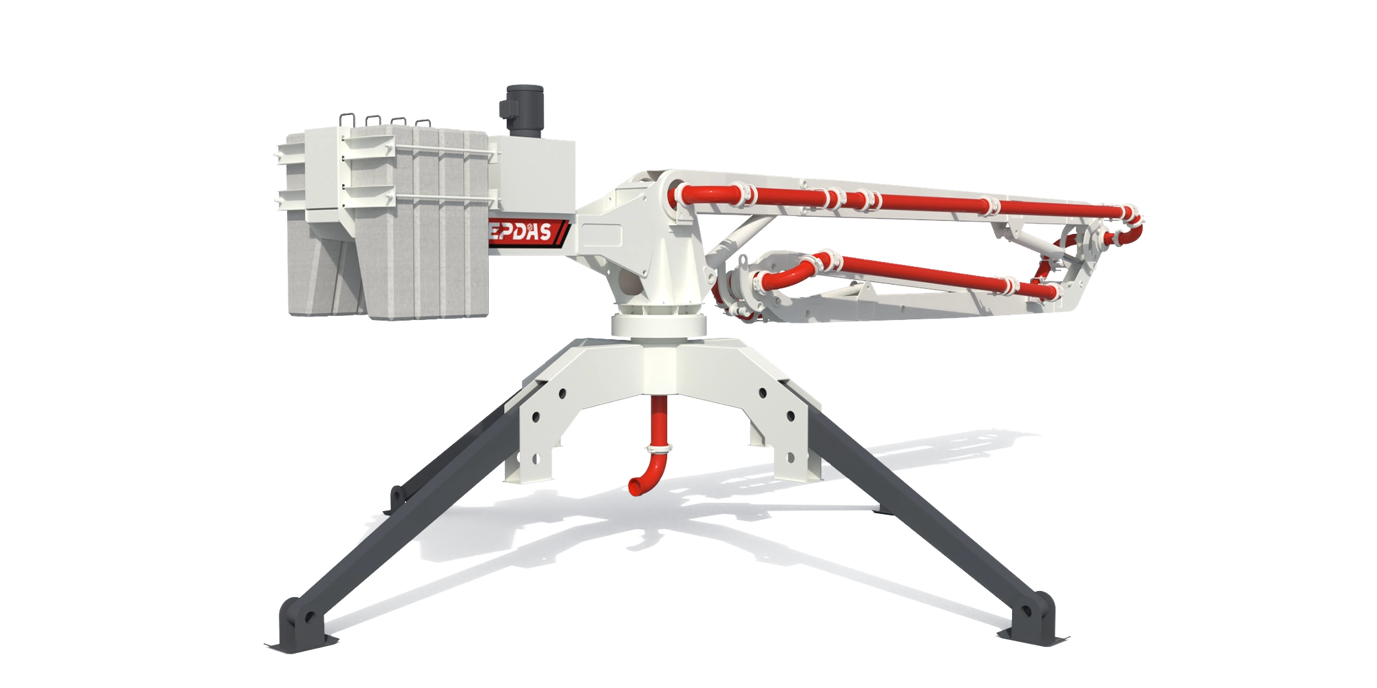 INTERFACE 03 / Spider Boom
A supported boom may distribute the supplied concrete.
Its pipe route must be included in the total pressure-loss calculation.
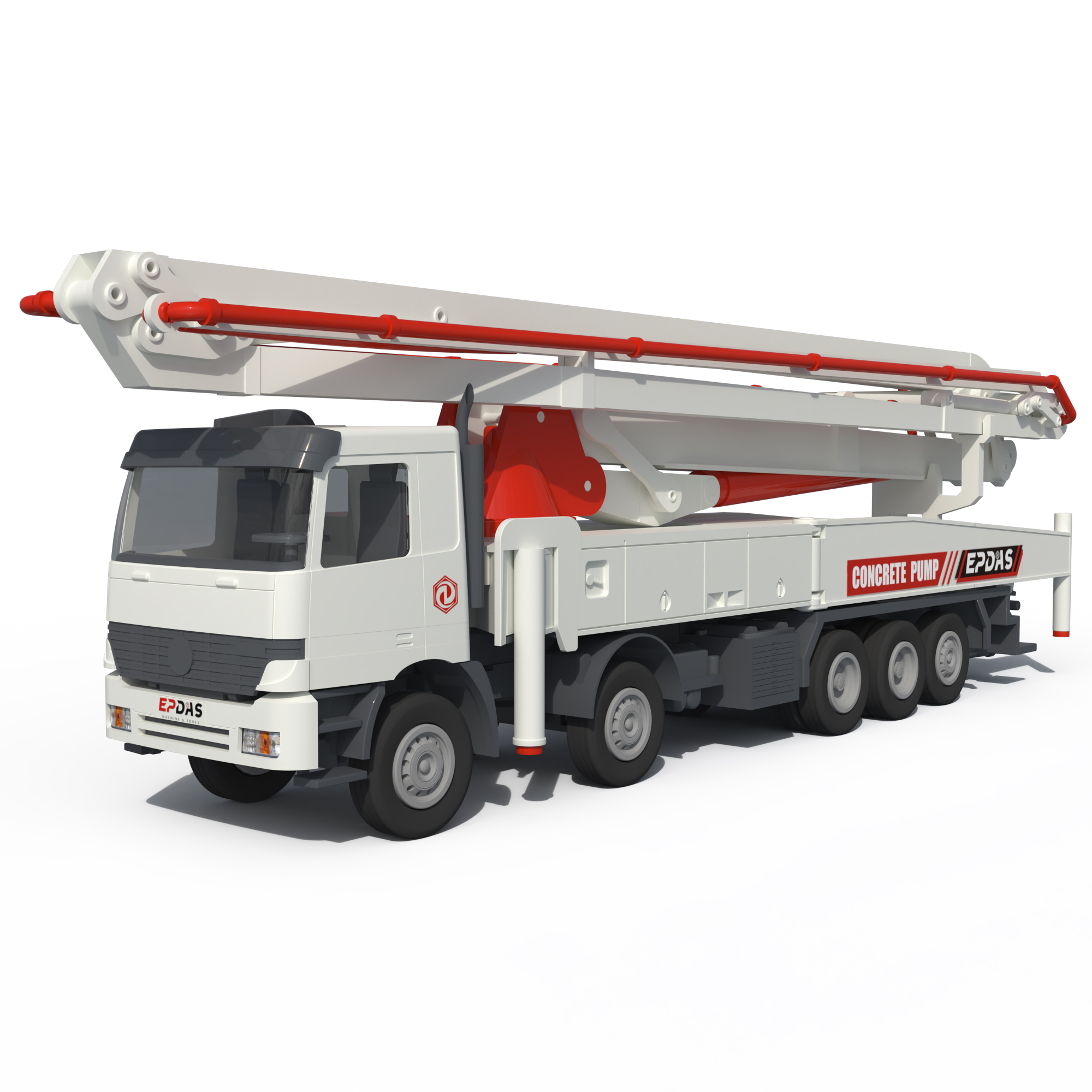 INTERFACE 04 / Concrete Boom Pump
An integrated truck-and-boom arrangement may avoid a different ground-line layout.
Compare working access and supports rather than motor power alone.
Options and alternative architectures are identified in each explanation. This is not a pre-approved matched package. Final connections, duty and supplied components require a model-specific technical review.
Review My Equipment CombinationSeparate the key systems to see what each contributes to the operation.
HBT60S-13-90 functional separation illustration. Blocks identify subsystem roles; they do not reproduce the machine geometry, assembly sequence or fastening details. Request the approved model drawing for engineering use.
| Parameter | HBT60S-13-90 |
|---|---|
| Theoretical max. discharging volume (m³/h) | 60 |
| Theoretical max. delivery pressure (Mpa) | 12.5 |
| Delivery distance Vertical (m) | 180 |
| Delivery distance Horizontal (m) | 700 |
| Distribution valve type | S valve |
| Hopper capacity (L) | 600 |
| Feeding height (mm) | 1400 |
| Inner dia. of delivery pipe (mm) | Φ125 |
| Main motor power (Kw) | 90 |
| Dimension (length ×width ×height) (mm) | 6170×1800×2100 |
| Overall weight (Kg) | 5100 |
Published EPDAS specifications are a reference for equipment selection. Final specifications and included equipment are confirmed in the quotation. Maximum output, pressure, vertical height and horizontal distance are separate reference limits. They are not simultaneous guaranteed operating points; concrete properties and pipe layout affect performance.
Original EPDAS Technical Reference ↗| Selection reference | HBT60S-13-90 · This model | HBT50S-12-55 | HBT80S-13-110 |
|---|---|---|---|
| Theoretical max. discharging volume (m³/h) | 60 | 50 | 80 |
| Theoretical max. delivery pressure (Mpa) | 12.5 | 12 | 12.5 |
| Main motor power (Kw) | 90 | 55 | 110 |
| Dimension (length ×width ×height) (mm) | 6170×1800×2100 | 5270×2000×1840 | 6170×1930×2100 |
| Overall weight (Kg) | 5100 | 3500 | 5200 |
Review this model for a regular external concrete supply and an electrical installation sized for the motor duty.
Theoretical max. delivery pressure (Mpa): 12.5
Hopper capacity (L): 600
Feeding height (mm): 1400
Confirm core equipment, options, buyer-provided systems, transport modules, inspection documents and support responsibilities in the quotation.